Building mesh and texture in MeshLab using point cloud produced by stereo reconstruction
The point cloud from a stereo reconstruction could be used in many ways. One of them is to be used to generate a 3D mesh and, further, the 3D model of the object in the real world. In this post, I will share my experience on mesh generation and texturing.
These days, I was working on generating meshes from 3D point cloud obtained from stereo reconstruction. The tools I am using is as follows:
- Stereo calibration and reconstruction by OpenCV.
- Mesh generation and texturing by MeshLab.
This post is arranged as
- Exporting the point cloud as a PLY file.
- Composing a MeshLab project (.mlp) file.
- Manual mesh generation and texturing.
- Batch mesh generation and texturing.
I experienced a lot of try-and-error loops as I walking through these processes. I would like to share those experiences here because somebody else may be working on similar projects and get frustrated about the situation that there are not enough tutorials that we could just watch and learn.
For this document, I was using Ubuntu 16.04. The MeshLab version is V1.3.2_64bit (Feb 19 2016), and MeshLab_64bit_fp v2016.12. Sorry for mixing the versions. I was working on my laptop and desktop at the same time. Well, I mean working at the lab and working from home.
1 Exporting the point cloud as a PLY file
In the sample code of OpenCV, it outputs the 3D point cloud into a PLY file. There are a couple of things that we should take care when we doing this.
1.1 Reprojecting to 3D space
If the OpenCV function reprojectImageTo3D( ) is used, we need the Q matrix that produced by the stereoRectify( ) function. This may means that we have to do the calibration ourselves by OpenCV. The other things that matter are that, as learned from the sample code of OpenCV, certain elements of Q should be modified to make the 3D point cloud lying along the right direction. If a zero-based indexing is used here, the following elements should be modified:
Q[1, 1] *= -1
Q[1, 3] *= -1
Q[2, 3] *= -1
The modified Q matrix makes the point cloud using a Y-axis parallel to the global Y-axis.
1.2 Dimension check
It is always a good idea to check the dimension inside MeshLab to see if the reprojected point cloud has the right special size. I use the “Measuring Tool” in figure 1 to measure the known distance between two points.

Figure 1 The “Measuring Tool” of MeshLab. ↑
1.3 Per-vertex information and UV coordinate
Sometimes we would like the PLY file to contain additional information. I face two issues when I was trying to figure out what I could put inside a PLY file. One is what kind of information is allowed to put into a PLY file. The other is what information MeshLab is expecting or MeshLab could make use of. Unfortunately, I have clear answers on none of them.
First of all, it seems to me that the PLY file format only makes constraints on the data type we could use, but not on the data itself. You could put anything you want as long as the data type is defined and the downstream program could recognize the data. But somehow, we always would like a list which makes it clear that what the “pre-defined” data people are using.
After some search, I found some useful information. One documentation of MATLAB summarized the data types often encountered in a PLY file. I think most of them MeshLab could recognize, but I did not test all of them. Particularly for our project, we want to bake a texture onto a mesh. The pipeline looks like this:
Table 1 Processing pipeline of this project. ↓
| Stereo images -> disparity map -> reprojected 3D point cloud -> mesh -> textured mesh |
|---|
The mesh and texture will be generated in MeshLab. So it becomes important how we could provide information about the texture along with the point cloud before the mesh is generated. In the beginning, we are looking for methods to do some sort of a manual UV mapping. The idea is simply that since the point cloud is generated by stereo reconstruction, we could just us the image from the base camera as the texture. The UV coordinates of each point in the point cloud could be easily calculated because we simply know the correspondence between a 3D point and a pixel in the image. However, the issue is how we gonna transfer this information all the way to the mesh which is generated later in MeshLab. The fact is I did not found one.
MeshLab does recognize per-vertex UV coordinates. I spend a long time trying to figure out what is the right way to supply this per-vertex information to MeshLab. Here are some web pages I found informative, but none of them helps.
- PLY file specifications with (face) texture coordinates.
- PLY file with UV data.
- MeshLab UV and Blender ST.
By examining the output file of MeshLab itself (ASCII format), I found that the right header for a PLY file containing per-vertex UV coordinates is as listed in table 2:
Table 2 Header of PLY file with UV coordinate. ↓
|
ply format ascii 1.0 comment VCGLIB generated comment TextureFile <texture_file> element vertex <number of vertices> property float x property float y property float z property uchar red property uchar green property uchar blue property float texture_u property float texture_v end_header |
Note that these instructions are CASE SENSITIVE! I spent a long time to get this lesson.
By using the above PLY header, we could ship the UV coordinate together with the spatial coordinate in a single PLY file, which contains only vertices but no faces.
Then the issue of information transfer comes into play. In short, I found no way to transfer the per-vertex UV coordinate to later generated mesh. At the moment we open a point cloud, no mesh is present. We could generate the mesh by Poisson Surface Reconstruction. The generated mesh is significantly coarse compared with my point cloud, meaning that there are fewer vertices. To transfer information from the dense point cloud to the vertices of the mesh, the nearest function I can find is “Filters->Sampling->Vertex Attribute Transfer”, as shown in figure 2. Unfortunately, it seems to me that MeshLab only supports information transfer in certain categories, without UV coordinate. So right now, I suppose there are no means for me to transfer the UV coordinates from the point cloud to the newly generated mesh. We have to perform parameterization and texturing later.
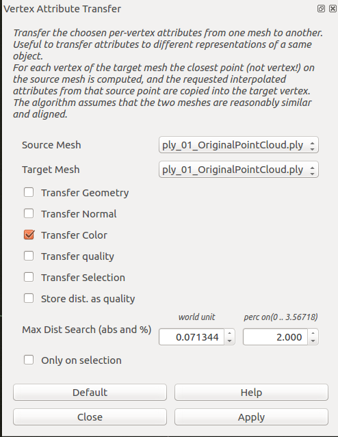
Figure 2 The Vertex attribute transfer dialog. ↑
1.4 Binary and ASCII modes
The last thing I would like to mention is that PLY file comes with two options for file mode, the ASCII and binary modes. Generally, binary mode is efficient both in file size and accessing speed. Binary mode is the default when doing a “save as” operation in MeshLab. But very limited resource could be found online to discuss how MeshLab handles a binary PLY. I did not succeed in doing it at the moment. Maybe I’ll try that later. If we take a closer look at the sample code of OpenCV, it does open a PLY file with the “binary write” mode. However, all of the later operations seems writing things in ASCII. And the resulting PLY file could be opened and read by a text editor.
In the course of finding the method for using binary mode, I found the following web pages are really interesting and helpful:
2 Composing a MeshLab project (.mlp) file
If we recall our processing pipeline in table 1, we know that we will do mesh parameterization and texturing later. One can always do the parameterization and texturing manually providing an appropriate image of the scene. We would like it to be as automatic as possible, because: We are doing stereo reconstruction. We know the correspondences between each point of the point cloud and the pixels of the base image (usually the left image). It should be easy to align the video image to the 3D point cloud and use the very image as the texture. We may have multiple point clouds which are produced by stereo reconstruction. We definitely want everything to be as automatic as possible. To do the parameterization and texturing, consider the above two things, we suggest to supplying MeshLab with the base image together with appropriate camera parameters. The aim is that once MeshLab gets the point cloud and the image, they are already aligned. We achieve it by first generating the point cloud as PLY file (no need of the per-vertex UV coordinate), then composing a MeshLab project (.mlp) file in which we supply the image with all the necessary camera information. The MeshLab project file also refers to the PLY file. When MeshLab opens the .mlp file, it imports the point cloud and the image automatically and it also sets the pose of the camera. In the .mlp file, we have to specify information about the point cloud, the image, and the camera. Here, table 3 is the .mlp file I generated. A .mlp file is essentially an XML file without the first line declaring the version of the XML.
Table 3 Sample .mlp file. ↓
1
2
3
4
5
6
7
8
9
10
11
12
13
14
15
16
17
18
19
<!DOCTYPE MeshLabDocument>
<MeshLabProject>
    <MeshGroup>
        <MLMesh filename="ply_01_OriginalPointCloud.ply" label="ply_01_OriginalPointCloud">
            <MLMatrix44>
1.000000 0.000000 0.000000 0.000000
0.000000 1.000000 0.000000 0.000000
0.000000 0.000000 1.000000 0.000000
0.000000 0.000000 0.000000 1.000000
</MLMatrix44>
        </MLMesh>
    </MeshGroup>
    <RasterGroup>
        <MLRaster label="Rectified_Left_color.jpg">
            <VCGCamera CameraType="0" CenterPx="2052 1513" FocalMm="16.6965299508" LensDistortion="0.000000 0.000000" PixelSizeMm="0.003460 0.003460" RotationMatrix="1.000000  0.000000  0.000000  0.000000  0.000000  1.000000  0.000000  0.000000  0.000000  0.000000  1.000000  0.000000  0.000000  0.000000  0.000000  1.000000 " TranslationVector="0.000000 0.000000 0.000001 1.000000" ViewportPx="4112 3008"/>
            <Plane fileName="Rectified_Left_color.jpg" semantic="1"/>
        </MLRaster>
    </RasterGroup>
</MeshLabProject>
In table 3, we could see the information MeshLab needs to properly load the point cloud and the image with camera parameters. Particularly, the attribute CenterPx (principal point) and FocalMm (focal length in millimeter) should be the values produced by the stereo calibration. We have to manually calculate the PixelSizeMm based on the sensor size (digital camera sensor size) and the image size. Normally, the calibration routine gives us the calibrated focal length measured in pixel. We have to convert the units from pixel into millimeter.
The key is using the rectified stereo image. Providing the rectified image, the pose of the camera is as trivial as the identity matrix and zero homogeneous vector. Thus, no rotation or translation for the camera.
Updated on July 19th, 2018: If the translation vector of the camera is [0.0 0.0 0.0 1.0], MeshLab won’t align the raster image and the 3D model when using the “show current raster mode” function (figure a). I do not know why. If the “show current raster mode” is wanted, then we could use a small coordinate shift instead of [0.0 0.0 0.0 1.0]. Say [0.0 0.0 1e-6 1.0] will do the trick. With this translation vector, MeshLab will align the raster to the 3D model when “show current raster mode” is activated. Also, note that in the project file listed in table 3, it is not allowed to use more than one white space between any numerical numbers of the translation vector. To be specific, the first of the following works but the second won’t work (“+” represents a single white space).
TranslationVector=”0.000000+0.000000+0.000001+1.000000”
TranslationVector=”0.000000++0.000000++0.000001++1.000000”
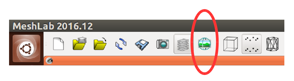
Figure a "show current raster mode" button. ↑
Updated on July 20th, 2018: The current version (2016.12) of MeshLab has a specific behavior such that the principle point defined by the attribute “CenterPx” is used to shift the position of the texture. When the principle point has a right shift from the center of the image, the texture will be shifted to the right, the opposite direction of the point cloud’s shift direction. The remedy to this is changing the values for “CenterPx” from the principle point (cx, cy) to ( w - cx, h - cy ), where cx and cy are the coordinates of the principle point, w and h are the width and height of the image.
To learn to compose a custom .mlp file, I just look into the ones saved by MeshLab. And I also find some useful web pages:
https://sourceforge.net/p/meshlab/discussion/499533/thread/cc40efe0/ https://sourceforge.net/p/meshlab/discussion/499533/thread/75dbb279/?limit=25
GitHub project 3DLIRIOUS/MeshLabXML
In my current code, which is Python, I use NumPy array to represent matrices and vectors. When composing an XML file with the help of some Python package, like the xml.etree.ElementTree, it actually needs a little trick to output NumPy array as plain text without brackets (“[” and “]”). I find the method here
https://stackoverflow.com/questions/9360103/how-to-print-a-numpy-array-without-brackets
Essentially, it is done by savetxt( ) using a string as the output.
People may also want their XML file to be “pretty”. Here are the pages I found helpful.
https://pymotw.com/2/xml/etree/ElementTree/create.html https://stackoverflow.com/questions/28813876/how-do-i-get-pythons-elementtree-to-pretty-print-to-an-xml-file
3 Manual mesh generation, parameterization, and texturing
With all the efforts we have made above, the process of mesh generation, parameterization and texturing is sort of standard. Basically, one can find tutorials on youtube or other video sites. The process is briefly outlined here: Compute the normal of the point cloud. Use Filters->Normals, Curvatures and Orientation->Compute normals for point sets. Build surface and mesh. Use Filters->Remeshing, Simplification and Reconstruction->Surface Reconstruction: Poisson. (Or equivalent menu entry in a newer version) Clean and modify the mesh if you wish. Make a backup copy before you do the cleaning or modification. Parameterization and texturing. Use Filters->Texture->Parameterization + texturing from registered rasters.
If everything works fine, you should get a textured mesh. The texture is the rectified image we provide earlier in the .wlp file.
However, there is always something behaves not as expected. When I was doing parameterization and texturing, I got partially black texture over some portion of the mesh. After lots of painful trails, I found that the option in figure 3 is the key to my problem. I do not know for sure what was happening inside MeshLab.
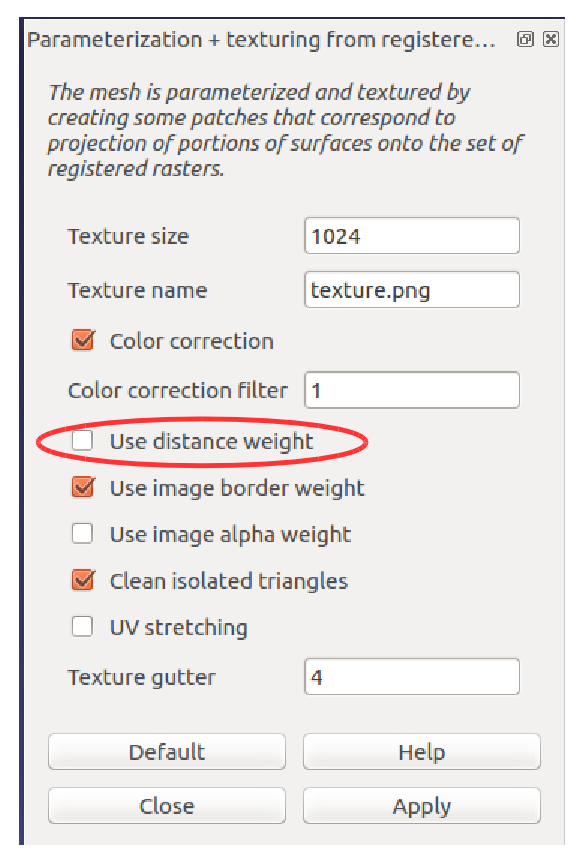
Figure 3 Parameterization and texturing dialog. ↑
I found that some other people had encountered the similar problem: https://sourceforge.net/p/meshlab/discussion/499533/thread/48f674a0/
4 MeshLab Server
As mentioned earlier, later we would like to process multiple point clouds automatically. Well, it could be done by submitting MeshLab script to MeshLab server.
MeshLab server is shipped with MeshLab. On my current Ubuntu system, if MeshLab is installed over snap, MeshLab server is called “meshlab.meshlabserver”. On other OS, it may take the name of “meshlabserver”.
While in MeshLab GUI, MeshLab records almost every filter operation you’ve made as you could save them to a script file. This is achieved by Filters->Show current filter scripts menu entry. By “almost”, I mean some user actions on the GUI is not recorded, and those could be vital for our process pipeline. To be specific, in our pipeline, we start from a point cloud and then generate the mesh. After the mesh generation, all subsequence operations are performed on the newly generated mesh only. We have to explicitly select the mesh in the “Layer Dialog” on the right side of the GUI. We “select” a mesh by clicking its label by our mouse. When we click the mouse, MeshLab actually performs a filter called “Mesh Layer->Change the current layer”, but it does not record it. So we may have to add this filter into the recorded script.
Sadly, I spent one of my entire night trying to work with MeshLab script because it performs differently in MeshLab GUI and MeshLab server. It really bothers me. Some of the recorded filters just won’t behave consistently, making either the GUI or the server crash with no meaningful error messages. I have to manually try each filter separately and then combine them in different patterns to get a sense of direction. Finally, I figured out a working solution.
First of all, MeshLab server won’t work properly with more than one mesh being loaded. That means after we generate our mesh from the point cloud, we could perform no further useful filters with the presence of multiple mesh layers. The solution is that I compose TWO separate .wlp files at the very beginning. One .wlp file refers to the original point cloud, the other one refers ONLY to the mesh generated by MeshLab and the rectified image with camera parameters. We use the first .wlp file to generate the mesh and use the second to perform parameterization and texturing. There is a catch, MeshLab does not provide us with any “filter” for “saving workspace” or “exporting mesh”. We have no control over the filename of some saved mesh. When MeshLab server saves the workspace based on the first .wlp file, it saves two new meshes. One mesh is a point cloud, the other is the newly generated mesh. And also, the original point cloud get overwritten. Let’s say the original point cloud is called A.ply, the newly saved point cloud is B.ply, and the newly generated mesh is C.ply. After MeshLab server’s processing:
- A is overwritten by a binary point cloud PLY file.
- B, which contains only the point cloud, has the newly computed normals but A doesn’t. And,
- B has the filename we specified on the command line (-o option) of MeshLab server, C has a fixed name which is “Poissonmesh_out.ply”.
Every time MeshLab server saves the workspace, a scenario similar to the above one happens. So we end up with several intermediate meshes lying in the folder. But hey, we accomplished what we meant to do. Not bad.
Here is a link where I got some hint.
5 Web pages that I came across and may be useful
Meshlab Stuff:
http://meshlabstuff.blogspot.com/
http://meshlabstuff.blogspot.com/2009/09/meshing-point-clouds.html
Failed to import mesh with polycubemap:
https://sourceforge.net/p/meshlab/bugs/85/
A discussion happened in a forum that recorded by Google:
https://groups.google.com/forum/#!topic/skanect/HBoixK8rdLc
A youtube video showing the working process of VisualSFM + MeshLab + Blender:
https://www.youtube.com/watch?v=Q-nwm03cjvw&index=2&list=PLtl-z5ok19vUnvt7vDPwEddqw7eJZsOGb
Photo Tourism:
http://phototour.cs.washington.edu/
Bundler:
http://www.cs.cornell.edu/~snavely/bundler/
6 Appendix
6.1 Check GPU usage
MeshLab makes extensive use of GPU. So you may want to monitor the resource status of the GPU. Here are some ways to do that:
- sudo pip install glances[gpu], sudo glances
- nvidia-smi –loop=1
- watch -d -n 0.5 nvidia-smi
6.2 Open MeshLab with stderr redirected
On my current computer, if I start MeshLab in a terminal, it constantly prints lots of error information regarding the GUI resource. I have to redirect the stderr for MeshLab to get a clear view.
>>> meshlab 2> /dev/null
Image courtesy
Cover image is copied from MeshLab official website.