Structural analysis with ANSYS Workbench and assembled mesh generated by ICEM CFD and Mesh component
For quite a long time that I was wondering if we could use the mesh generated by ICEM CFD to do a structural analysis. And I am also curious that if we could combine, assemble, or merge meshes which are generated by different software in various disciplines. Today I got a chance that to perform a structural analysis that will assemble meshes from ICEM CFD and the Mesh component of ANSYS Workbench.
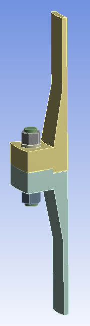
The objective under question is a bolted flange connection. One of my colleagues would like to calculate the stress and strain of the flanges and the bolt. The geometry is so simple that I could generate the mesh using ICEM CFD. This should be a good chance to give it a try.
The aim is to generate meshes for the flanges by ICEM and create another mesh using the Mesh component of ANSYS Workbench. Then, somehow, combine these meshed together to get the final mesh for the structural analysis. After lots of try-error-and-correct procedures on my computer, I finally figured out the correct approach to do this.
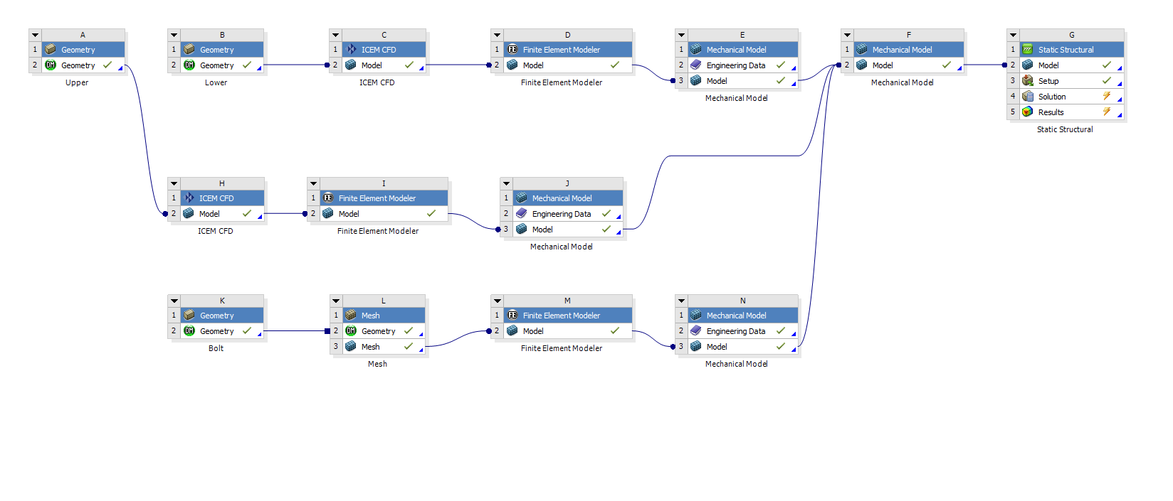
The following image shows the overall project schematic in the ANSYS Workbench. The original image with full resolution is here.
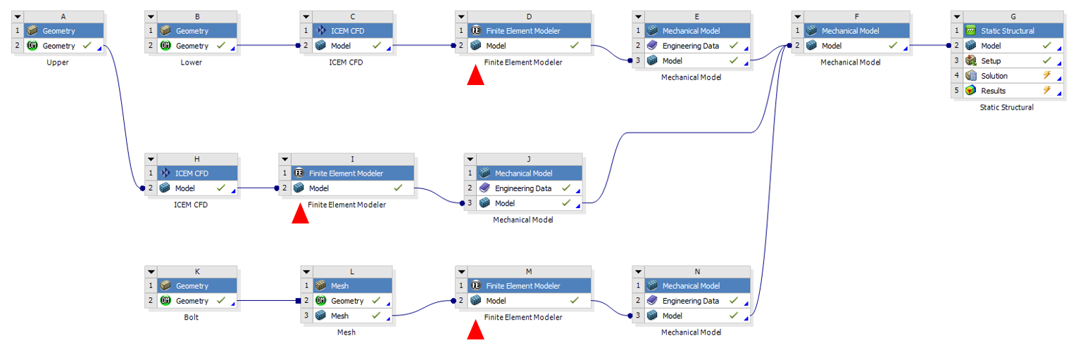
The key process is using the “Finite Element Modeler” component to convert different kinds of meshes into finite element representation. Without this component, I could not find a way to transfer or combine meshes into a single finite element model. Use the “Mechanical Model” component to further convert the finite element representation into a valid mechanical model that ANSYS Workbench or APDL could process. Every mesh will result in a “Mechanical Model”, then it’s time to combine all the models into one single Mechanical Model. Once the single Mechanical Model is ready, we could easily share its data to a “Static Structural” component. The three Mechanical Models marked by red triangles (as shown in the above image) provide us a chance to set different engineering data individually according to each meshed component. In the final Static Structural component, the mesh is ready to go since it is already created and properly converted. After defining a set of proper boundary conditions and loads, we could run the solver and get our solution.
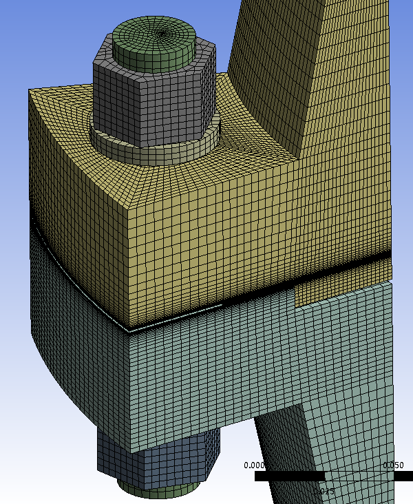
The following figure shows the assembled mesh in the final Static Structural component. And we could see that there are some contacts that already been created for you.